 |
nrf24L01
1.0
nrf24L01 library
|
Test program for receiving data with a Nordic NRF24L01p and a Xmega. More...
#include <avr/io.h>#include <avr/interrupt.h>#include "nrf24/nrf24spiXM2.h"#include "nrf24/nrf24L01.h"Macros | |
| #define | F_CPU 2000000UL |
Functions | |
| void | init_pwm (void) |
| Initializes pin 0 of port C as PWM ouput. More... | |
| void | init_nrf (void) |
| Initializes nrf24L01+. More... | |
| int | main (void) |
| main routine for receiver More... | |
| ISR (PORTF_INT0_vect) | |
| Interrupt function for receiving data. More... | |
Variables | |
| uint8_t | pipe [5] = {0x48, 0x76, 0x41, 0x30, 0x31} |
| pipe address is "HvA01" More... | |
| uint8_t | packet [32] |
| buffer for storing received data More... | |
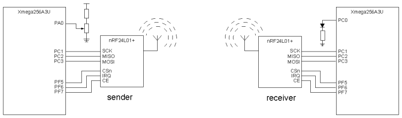
Test program for receiving data with a Nordic NRF24L01p and a Xmega.
The hardware configuration consists of a sender and a receiver. This file contains the program for the receiver. The sender is in file nrf24_test_send.c. The receiver is just a HvA-Xmegaboard with nothing connected. The led is the blue led.
#include lines.This test program is based on the example in paragraph E.1 from 'De taal C en de Xmega'
| #define F_CPU 2000000UL |
| void init_nrf | ( | void | ) |
Initializes nrf24L01+.
This function is almost the same as the init_nrf() of the sender. The interrupt is enabled. The interrupt pin is pin 6 of port F and responses to a falling edge.
Only a pipe for reading opened and the radiomodule is set in the receive mode.
This routine is code E.3 from 'De taal C en de Xmega' second edition, see Voorbeelden uit 'De taal C en de Xmega'
This function is almost the same as the init_nrf() of the receiver. There are two pipes. One for sending the value and one for the acknowledge
This routine is code E.1 from 'De taal C en de Xmega' second edition, see Voorbeelden uit 'De taal C en de Xmega'
| void init_pwm | ( | void | ) |
Initializes pin 0 of port C as PWM ouput.
With F_CPU is 2 MHz the frequency will be 200 Hz
This routine is code E.5 from 'De taal C en de Xmega' second edition, see Voorbeelden uit 'De taal C en de Xmega'
| ISR | ( | PORTF_INT0_vect | ) |
Interrupt function for receiving data.
If the interrupt is caused by the received data a data packet is read and assigned to CCABUF of timer/counter0 of port C.
This routine is code E.6 from 'De taal C en de Xmega' second edition, see Voorbeelden uit 'De taal C en de Xmega'
| int main | ( | void | ) |
main routine for receiver
It initializes the nrf24L01+ and the pwm output and enables the interrupt mechanism. It does nothing. The program just waits for an interrupt of the nrf24L01+.
This routine is code E.4 from 'De taal C en de Xmega' second edition, see Voorbeelden uit 'De taal C en de Xmega'
| uint8_t packet[32] |
buffer for storing received data
| uint8_t pipe[5] = {0x48, 0x76, 0x41, 0x30, 0x31} |
pipe address is "HvA01"
 1.8.6
1.8.6 
